Installation
The trap, flap valve, catch bag and funnel net should be assembled and positioned according to the instructions provided with the trap. Ensure that the draw string and toggle of the catch bag are both tucked into the trap (i.e. that they do not protrude from the trap) to allow a good seal between the flange of the flap valve and the cover of the trap. The 12 V outdoor power supply supplied with the trap must be plugged into a water-safe 100 – 240 VAC power outlet.
The sensor should be lowered over the flap valve of the trap, such that the flap valve enters the circular opening in the base of the sensor. The base of the sensor then rests on the flange of the flap valve. The placement of the Vectrack sensor on a BG-Mosquitaire trap is shown in Figure 4.
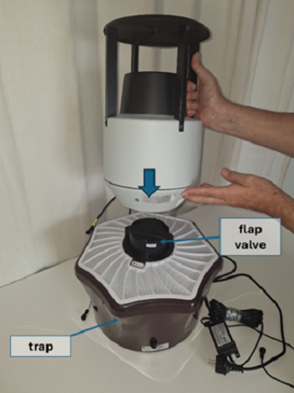
Figure 4 – Placement of the Vectrack sensor on a trap
Important: The sensor should be placed in a location with a fair to strong 2G / 4G (LTE-M) cellular network signal, to enable it to communicate with the server. The operator’s mobile phone may be used to indicate signal strength at the site, and a strength of at least two bars is recommended. It is also recommended to choose a location which is not overly dusty, to minimize the impact of dust accumulation on the internal flight tube of the sensor (see Section 5. Cleaning and Maintenance).
The trap cable is connected to the trap as shown in Figure 5. Ensure by sight or by feel that the bump and notch on the connectors are aligned before pushing them together. The locknut on the cable connector should then be tightened by hand.
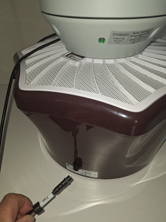
Figure 5 – Connecting the sensor trap cable to the trap.
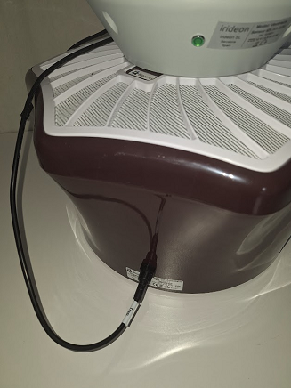
Figure 6 – Sensor trap cable fitted, with the locknut tightened.
The power cable from the sensor is connected to the 12 VDC supply as shown in Figure 7. Ensure by sight or by feel that the notch and bump on the connectors are aligned before pushing them together. The lock nut on the 12 VDC connector should then be tightened by hand.
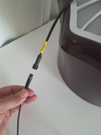
Figure 7 – Connecting the sensor power cable to the 12 VDC supply.
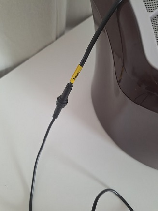
Figure 8 – Sensor power cable connected to the 12 VDC supply, with the locknut tightened.
Figure 9 shows the sensor mounted on a trap with the sensor’s power cable connected to a 12 VDC power supply and the sensor’s trap cable connected to the trap, to power the suction fan in the trap.
The suction fan creates a downward flow of air through the sensor. Insects which fly close to the inlet funnel of the sensor may then be sucked into the inlet funnel and down through the sensor and into the catch bag in the trap.
To inspect or replace the catch bag in the trap, the sensor should be lifted off the trap and placed on the ground. There is no need to disconnect the Power or Fan cables during the process.
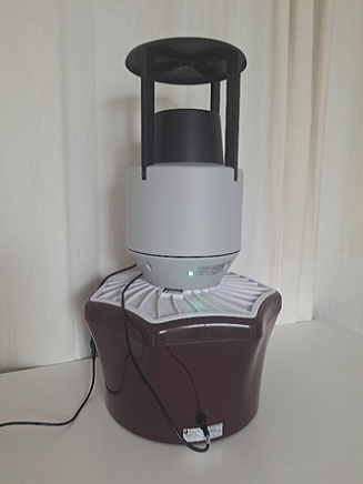
Figure 9 – Vectrack sensor mounted on a trap, with the Power and Trap cables connected.
Confirmation of Correct Operation
After connecting 12 VDC power to the sensor, the sensor will progress through a series of operating modes (1 to 4), each indicated by the green status LED, as shown in Table 1.
| Mode | Duration | Status LED | Fan | Notes |
|---|---|---|---|---|
| 1 | ~10 s | Fully ON | OFF | The LED will turn on ~3 s after power is applied. |
| 2 | ~30 s | Fully ON | ON1 | The sensor will try to register with the available 2G/4G (LTE-M) cellular network, and if it can’t, it will return to Mode 1. |
| 3 | ~1 min typ.2 | “Fast-flash”3 | ON | The sensor will try to connect to the server via the available 2G/4G (LTE-M) cellular network, and if it can’t, it will return to Mode 1. |
| 4 | Ongoing | “Slow-flash”4 | ON | The sensor and trap are now ready to detect insect events. The LED will fast flash every 30 mins when the sensor sends recordings to the server, or when the sensor receives a firmware update from the server. If an error occurs, the sensor will return to Mode 1. |
Table 1 – Sensor operating modes and status LED indication
After installation, the installer should listen for the fan noise to ensure that the trap cable has been connected and observe the status LED to ensure that the sensor reaches Mode 4 before leaving the site.
On subsequent visits to the site, the user should check that the fan is operating and that the sensor is in the slow-flash state (Mode 4).